Beyond Sight: The Physics and Practical Meanings of Thermal Imaging
Update on Oct. 8, 2025, 8:43 a.m.
Our eyes are remarkable instruments, tuned to perceive a narrow sliver of the vast electromagnetic spectrum we call visible light. Yet, this is but a fraction of the reality that surrounds us. Beyond the violet, lies the energetic realm of ultraviolet and X-rays. And just past the red, stretching into wavelengths our biology cannot detect, is the world of infrared—the world of heat. This is not the reflected light we are used to, but a fundamental glow emitted by every object in the universe with a temperature above absolute zero. It’s the unseen light that allows the James Webb Space Telescope to peer through cosmic dust and witness the birth of stars. It’s also the light that, with the right tools, can reveal a faulty circuit breaker hidden in a wall, a moisture leak creeping into a ceiling, or the subtle heat signature of a failing machine bearing.
This article is a journey into that unseen spectrum. We will explore the core physics that governs thermal energy and demystify how a thermal imaging camera translates this invisible radiation into a vibrant, informative picture. Using the AOPUTTRIVER Rechargeable Infrared Thermal Camera, a capable and accessible device, as a practical example, we will decode the technical specifications that define a camera’s power and its limits. This is not a product review; it is an exercise in understanding, designed to equip you with the knowledge to look at any thermal imager and see beyond the marketing, into the science itself.

The Fundamental Principle: Everything Glows
At the heart of thermal imaging lies a simple yet profound concept: every object, from a block of ice to a bar of molten steel, is constantly emitting energy in the form of infrared radiation. This phenomenon, known as thermal radiation, was first rigorously described by Max Planck at the dawn of the 20th century. His work on blackbody radiation revealed that the intensity and peak wavelength of this emitted energy are directly tied to an object’s temperature.
Imagine heating a piece of iron in a forge. At first, it just gets hot, emitting radiation entirely in the infrared. As its temperature climbs, it begins to glow a dull red, then bright orange, and finally a brilliant white-blue. What you are witnessing is Planck’s law in action: as the temperature rises, the emitted energy increases dramatically, and the peak of that emission shifts to shorter, more energetic wavelengths, eventually entering the visible spectrum.
A thermal camera does not need an object to be “red hot” to see it. It is sensitive enough to detect the far more subtle infrared emissions from objects at everyday temperatures. It achieves this using a focal plane array (FPA) of microscopic sensors called microbolometers. Each microbolometer in the array is, in essence, a tiny, highly sensitive thermometer. When infrared radiation from a target strikes a microbolometer, its temperature changes minutely. This change in temperature alters its electrical resistance, which is then measured and converted into a digital signal. The camera’s processor takes the signals from thousands of these microbolometers and assigns a color or shade of gray to each one based on its intensity, painting a detailed thermal map we call a thermogram.

Decoding the Spec Sheet: What the Numbers Truly Mean
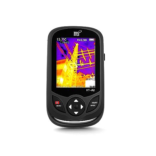
A thermal camera’s specification sheet can be intimidating, filled with numbers and acronyms. But understanding a few key parameters is all it takes to move from a casual user to an informed analyst. Let’s use the AOPUTTRIVER camera’s specifications to illustrate.
Resolution (210x160 Pixels): Your Level of Detail
Just like a digital camera, a thermal imager has a resolution, which refers to the number of microbolometer pixels on its sensor. The AOPUTTRIVER has a 210x160 array, meaning it has 33,600 individual temperature-measuring pixels. More pixels mean more detail and a clearer image, allowing you to distinguish smaller temperature anomalies from further away.
However, resolution tells only part of the story. A more practical metric for professionals is the Instantaneous Field of View (IFOV), which measures the spatial resolution, or the smallest area a single pixel can see at a given distance. In short, resolution tells you how many pixels you have, while IFOV tells you what each of those pixels is actually seeing. While not explicitly stated for this camera, we can understand the concept: a camera with a higher pixel count and quality optics will have a smaller IFOV, enabling it to accurately measure the temperature of smaller targets, like an overheating electrical lug on a distant motor controller. With 33,600 points of measurement, a camera like this is well-suited for inspecting larger components like circuit breaker panels or HVAC ductwork, but might struggle to get an accurate reading on a tiny surface-mount resistor from across a room.
Refresh Rate (9Hz): Capturing a Fluent World
The refresh rate, measured in Hertz (Hz), tells you how many times per second the thermal image is updated. The AOPUTTRIVER has a 9Hz refresh rate. This means you see nine distinct frames every second. For most maintenance and inspection tasks, where you are scanning stationary objects like walls, pipes, or electrical panels, 9Hz is perfectly adequate. It provides a smooth-enough image to pan around and locate anomalies without significant lag.
You may see more expensive cameras advertised with 30Hz or 60Hz refresh rates. These higher rates are crucial for applications involving fast-moving objects or rapidly changing thermal events, such as in research and development or certain automotive diagnostics. It’s worth noting that the 9Hz standard is common in consumer-grade thermal cameras partly due to international export regulations, which often restrict the sale of higher-frequency imagers.
Thermal Sensitivity (NETD): Seeing the Subtlest Differences
Perhaps the most important and often overlooked specification is Thermal Sensitivity, or Noise Equivalent Temperature Difference (NETD). Measured in millikelvins (mK), it defines the smallest temperature difference the camera can detect. A lower NETD number is better. A camera with an NETD of 50mK can distinguish temperature variations as small as 0.05°C, while one with 100mK can only see differences of 0.1°C or more.
Think of it as the signal-to-noise ratio for heat. A low NETD camera is like being in a very quiet room where you can hear the faintest whisper; a high NETD camera is like trying to hear that same whisper in a noisy environment. The AOPUTTRIVER product page does not list an NETD value, which is common for entry-level devices. While it is likely sufficient for detecting significant hot spots (like a 20°C rise on a motor), it might lack the sensitivity needed for applications like building diagnostics, where detecting the subtle 0.5°C difference caused by slight moisture in a wall requires a more sensitive instrument. When evaluating any thermal camera, asking for the NETD is a hallmark of an informed buyer.
The Art of Measurement: Beyond Just Pretty Pictures
Possessing a thermal camera is one thing; using it to gather accurate, reliable data is another entirely. A thermogram is not just a picture; it’s a map of radiated energy, and its accurate interpretation requires understanding a few key concepts.
The Crucial Role of Emissivity
Emissivity is a measure of how efficiently a surface emits thermal energy compared to a perfect emitter (a theoretical “blackbody”). It’s a value between 0 and 1. A matte black surface has an emissivity close to 1, meaning the infrared radiation it emits is a very accurate representation of its true surface temperature. Conversely, a shiny, reflective surface like polished aluminum has a very low emissivity (perhaps 0.1). It is a poor emitter of its own heat and an excellent reflector of the thermal energy from its surroundings.
Imagine pointing a thermal camera at a hot cup of coffee in a ceramic mug next to one in a stainless-steel travel mug. The ceramic mug (emissivity ~0.95) will appear very hot, and the camera’s temperature reading will be accurate. The stainless-steel mug (emissivity ~0.2) will appear much cooler, and its reading will be wildly inaccurate because it’s primarily reflecting the thermal energy of everything around it—your body, the ceiling lights, the sky. To get an accurate reading, professional thermographers either adjust the emissivity setting on their camera to match the material they are measuring or, more practically, they place a small piece of high-emissivity material, like black electrical tape, on the surface to create a reliable measurement spot.
Palettes: Translating Data into Insight
The colors on a thermal image are a human invention. The camera’s sensor sees only in shades of intensity, and a color palette is applied to this data to make it easier for our brains to interpret. The AOPUTTRIVER offers four common palettes, each with its own purpose:
- White Hot / Black Hot: These are grayscale palettes where hotter areas are either white or black. They are excellent for quickly identifying the absolute hottest or coldest spots in a scene due to their simplicity and high contrast.
- Iron Red (Ironbow): This popular palette uses a gradient from black and purple for cold, through yellows and oranges for mid-tones, to bright white for the hottest areas. It provides intuitive, high-contrast imagery that is easy to interpret.
- Rainbow: This palette uses the full visible spectrum to show temperature distribution. While visually striking, it can sometimes introduce perceived temperature shifts where none exist due to the sharp transitions between colors (e.g., from green to yellow). However, it is invaluable for visualizing complex thermal patterns and small temperature differences within a scene.
Choosing the right palette is about matching the tool to the task. For a simple “go/no-go” check, Iron Red is often best. For a detailed analysis of airflow, a Rainbow palette might reveal more.

Conclusion: From Invisible Light to Actionable Insight
Thermal imaging is not magic; it is the application of fascinating and well-understood physics. By grasping the principles of thermal radiation, you can begin to appreciate the incredible power of these devices. By learning to decode their specifications—understanding that resolution dictates detail, refresh rate governs fluidity, and sensitivity determines subtlety—you transform from a mere operator into a knowledgeable analyst.
We have seen that a camera’s utility is defined not just by its hardware, but by the user’s understanding of concepts like emissivity and the strategic use of tools like color palettes. The AOPUTTRIVER camera, with its accessible feature set, serves as an excellent vehicle to learn and apply these principles. You now possess the foundational knowledge to not only use such a tool effectively but also to critically evaluate any thermal imaging device, understanding its strengths and recognizing its limitations.
You’ve learned the theory behind seeing the unseen. Now, it’s time to put that theory into practice. In our next article, we will take these concepts into the field, exploring step-by-step guides for using a thermal camera to diagnose real-world problems in electrical systems, building envelopes, and mechanical equipment.